Thrust Mapper - Systems of Equations
Meet Bradbury
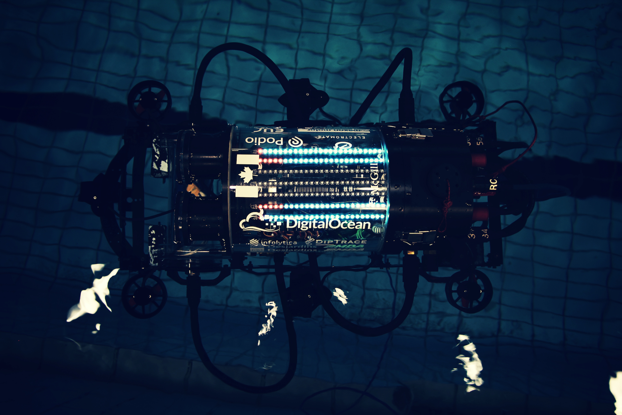
This is Bradbury. He’s an autonomous underwater vehicle (AUV). One of the greatest parts of my undergrad has been working with Bradbury and the rest of the McGill Robotics team. I’ve spent a lot of time working with different versions of this AUV, starting as a clueless new roboticist in U1 all the way to a marginally less clueless software lead.
Thrust Mapper
One of the most important components of Bradbury’s software stack is Thrust Mapper. It’s only about a hundred lines of python (even less without comments!) but it’s responsible for taking in directions and spitting out motor voltages.
Inputs
More specifically, thrust mapper takes in two vectors that represent a desired effort in those directions. The first vector is the translational effort, \(F\), which gives the \(x, y\) and \(z\) directions. Because our robot runs in water, we use the nautical terms surge, sway, and heave respectively.
$$ F = \begin{bmatrix} x \\\ y \\\ z \end {bmatrix} = \begin{bmatrix} surge \\\ sway \\\ heave \end {bmatrix} $$
The second vector is the rotational effort, \(M\), or movement around the axes. Here the directions are known as roll, pitch, and yaw.
$$ M = \begin{bmatrix} m_x \\\ m_y \\\ m_z \end {bmatrix} = \begin{bmatrix} roll \\\ pitch \\\ yaw \end {bmatrix} $$
Outputs
Bradbury is equipped with 8 T100 thrusters from Blue Robotics. Thrust Mapper takes the vectors described in the previous section, and outputs the voltage required on each thruster to get the desired effort.
The figure below illustrates how they are mounted to the robot as if looking at the robot from above.
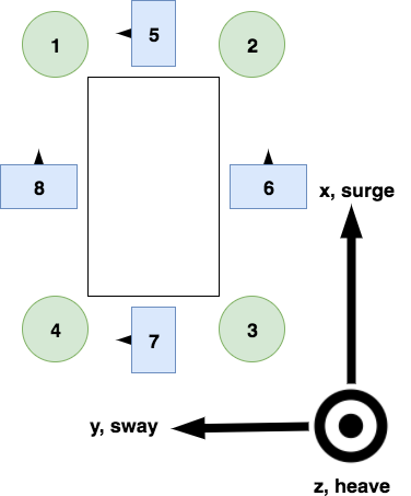
The figure above shows 4 in-plane thrusters in blue with the arrow heads indicating the positive direction of force.
There are also 4 out-of-plane thrusters, show in green. All these thrusters have positive force in the direction of the heave vector. In this picture, that is out of the page.
This distinction between in-plane and out-of-plane thrusters is helpful because they help us identify which thrusters can help us with which efforts. For instance, no matter how much or little force is produced by thrusters 1, 2, 3, and 4 they cannot help Bradbury move forward. Same goes for thrusters 5, 6, 7, and 8 if we want to adjust the pitch of the robot (that is, the angle at which bradbury’s nose is pointed).
Explaining all this in words can be cumbersome, so lets leverage a little linear algebra.
A Couple Vectors
Let’s put the two sets of thrusters into vectors,
$$
T_{out} =
\begin{bmatrix}
T_1 \\\
T_2 \\\
T_3 \\\
T_4 \end
{bmatrix},
T_{in} =
\begin{bmatrix}
T_5 \\\
T_6 \\\
T_7 \\\
T_8 \end
{bmatrix}
$$
Ultimately, we want to get a classic system of equations \(Ax = b\), where \(x\) is the vector representing the force provided by each thruster and b is the desired effort.
In-Plane Thrusters
Let’s start with the in-plane thrusters, \(T_{in}\).
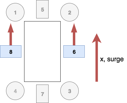
We need to identify which directions these thrusters can help us achieve. First off, we can see that if we provide equal force with thrusters 6 and 8, we’ll get a surge, \(F_x\).
Doing the same thing, but with 5 and 7 instead, will give us a sway, \(F_y\).
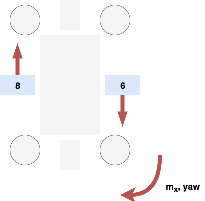
But what happens if, instead of providing equal forces with symmetric thrusters, we give them opposite forces. In that case, we start spinning about the \(z\) axis - yaw, \(m_z\).
Using these relationships, we can set up a system of equations that looks like this,
$$ A \begin{bmatrix} T_5 \\\ T_6 \\\ T_7 \\\ T_8 \end {bmatrix} = \begin{bmatrix} F_x \\\ F_y \\\ M_z \end {bmatrix} $$
But what is \(A\)?
Well, first off, we know the shape of \(A\). It is being multiplied on the right by a vector with 4 entries - so it must have a width of 4. Furthermore, the output of this transform is a vector with 3 entries - so it must have a height of 3.
$$ A = \begin{bmatrix} a_{00} & a_{01} & a_{02} & a_{03} \\\ a_{10} & a_{11} & a_{12} & a_{13} \\\ a_{20} & a_{21} & a_{22} & a_{23} \end {bmatrix} $$
One way we can read this matrix is: “\(a_{ij}\) is the contribution of the \(j^{th}\) thruster to the \(i^{th}\) direction.
For example, \(a_{02}\) tells us how much \(T_6\) will contribute to \(F_x\). In this case, it’s \(0\) because \(T_6\) is orthogonal to x; it can’t give any help in the x direction because it doesn’t point that way at all!
A few other entries represent a similar situation so we can put zeroes in all those spots:
$$ A = \begin{bmatrix} 0 & a_{01} & 0 & a_{03} \\\ a_{10} & 0 & a_{12} & 0 \\\ a_{20} & a_{21} & a_{22} & a_{23} \end {bmatrix} $$
Another easy case is when thrusters are parallel to the directions. We get a contribution equal to the force provided by those thrusters, so we can just put \(1\)s in there:
$$ A = \begin{bmatrix} 0 & 1 & 0 & 1 \\\ 1 & 0 & 1 & 0 \\\ a_{20} & a_{21} & a_{22} & a_{23} \end {bmatrix} $$
But what to do with that pesky bottom row? This row represents rotational effort, so we’re going to have to consider torque.
$$ M = r \times F $$
That little \(r\) is the distance to the axis of rotation. We have to take these measurements on Bradbury, but to keep things tidy here, let’s introduce the notation \(r_{ij}\) which denotes the distance of Thruster \(i\) from axis \(j\). That should be enough to fill in the rest of the matrix!
$$ A = \begin{bmatrix} 0 & 1 & 0 & 1 \\\ 1 & 0 & 1 & 0 \\\ r_{5z} & r_{6z} & -r_{7z} & -r_{8z} \end {bmatrix} $$
Notice the entries corresponding to thrusters 7 and 8 are negative. If we use the right hand rule, we see that those thrusters point opposite to the direction of rotation - the negatives account for that fact.
This provides us with all we need to set up our system of equations.
$$ \begin{bmatrix} 1 & 1 & 0 & 0 \\\ 0 & 0 & 1 & 1 \\\ r_{5z} & r_{6z} & -r_{7z} & -r_{8z} \end {bmatrix} \begin{bmatrix} T_5 \\\ T_6 \\\ T_7 \\\ T_8 \end {bmatrix} = \begin{bmatrix} F_x \\\ F_y \\\ M_z \end {bmatrix} $$
Out-of-Plane Thrusters
We can go through the same process to figure out the equivalent matrix for the out-of-plane thrusters. Hopefully you can convince yourself we get this system:
$$ \begin{bmatrix} r_{1x} & r_{2x} & -r_{3x} & -r_{4x} \\\ -r_{1y} & -r_{2y} & r_{3y} & r_{4y} \\\ 1 & 1 & 1 & 1 \end {bmatrix} \begin{bmatrix} T_1 \\\ T_2 \\\ T_3 \\\ T_4 \end {bmatrix} = \begin{bmatrix} M_x \\\ M_y \\\ F_z \end {bmatrix} $$
Wrap Up
So far we’ve organized our thrusters into a system of equations to solve for our direction efforts. Now we can just find the inverse of \(A\), multiply by our inputs, and get a solution, right?
Well, not quite. First off, \(A\)’s not invertible. Also, turns out not everything in the real world is linear.
But that’s a discussion for the next post.